SYSTEMS DESIGNED AROUND YOUR BUILDING'S RISK

Fire detection engineering for your building

We plan detection, evacuation and automation as one fire strategy for industrial sites, hotels, shopping centres, healthcare buildings and campuses.

EVERY FACILITY HAS A DIFFERENT FIRE RISK

We select detectors for the risk, not just the building

The same equipment list will not suit every site. Ceiling height, airflow, fire load, operations and evacuation arrangements are assessed together.

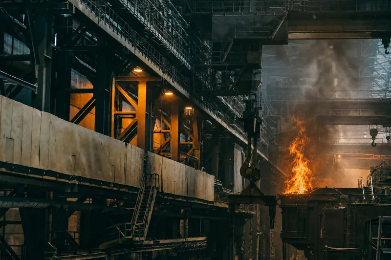
Production facility with large industrial machinery

01

Production facilities

Factory

KEY RISK
Dust, heat, process-related false alarms and continuity of production.
DETECTION APPROACH
Multi-sensor, flame and linear heat detection, with addressable cause-and-effect integration.

Logistics warehouse with palletised goods on high racks

02

Logistics centres

Warehouse

KEY RISK
High ceilings, obstructed sight lines and a fire load that can develop rapidly.
DETECTION APPROACH
Beam or OSID detection, in-rack detection and zoned evacuation arrangements.

Wide, well-lit corridor in a modern hospital

03

Healthcare buildings

Hospital

KEY RISK
Continuous operation, people with limited mobility and controlled evacuation.
DETECTION APPROACH
Addressable detection integrated with fire doors, lifts and phased evacuation.

DIFFERENT BUILDINGS, THE SAME ENGINEERING DISCIPLINE

Our work is not limited to these three examples.
We plan detection around the building's use, evacuation arrangements and risk, rather than its name alone.

Hotels and HospitalityNight-time occupancy and phased evacuation
Shopping Centres and RetailHigh footfall and large spaces
Campuses and EducationMultiple buildings and central monitoring
Offices and Mixed-Use BuildingsFloor-by-floor scenarios and integration
Data CentresVery early warning and business continuity
Transport BuildingsLong routes and smoke control

DETECTION FOR CHALLENGING ENVIRONMENTS

Detection suited to demanding conditions

High ceilings, dust, air movement and early-warning requirements call for a solution selected around the site's risk.


High-rack warehouse illustrating a beam detector application

Beam

TS EN 54-12

Beam detection for high ceilings

Detects smoke along an optical beam across large, hard-to-reach spaces.

Warehouses, hangars, sports halls and high production spaces

FIRE SAFETY AUTOMATION

One coordinated scenario, from alarm to safe evacuation

See how detection, location identification, security monitoring, building controls and evacuation work together.

The example shows fire detection, address confirmation at a security repeater panel, notification, building controls, evacuation and fire service intervention.

Functions are determined by the building's fire strategy, mechanical and electrical designs, and applicable regulatory requirements.

GAS AND FLAME DETECTION

Monitor gas and flame at an early stage

We monitor combustible or toxic gases, oxygen levels and open-flame risks using suitable field detection equipment.


Replaceable sensor cartridge
Selected for the target gas and measurement range.

Fixed gas transmitter with its lower sensor cartridge removed, alongside an optical flame detector


Gas transmitterppm, %LEL, %Vol

Flame detectorUV/IR, IR3

A STANDARDS-BASED PROCESS

A controlled process, from design to site testing

We consider the relevant standards throughout design, installation and site testing.

TS CEN/TS 54-14Application guidance from planning through maintenance
TS EN 54Product standards for system components
VdS 2095Planning and installation criteria where specified by the project

Design
Installation
Site testing

Risk and fire scenarios are planned, then alarm, fault and control functions are tested on site and handed over with records.

DIFFERENCES BETWEEN SYSTEMS

Compare systems against your project's requirements

Building size, continuity of operations, control requirements, existing cabling and maintenance arrangements all influence system selection.

Comparison ConventionalZone-based system AddressableLarge and complex buildings Wireless addressableAddressable devices with radio communication
Typical application Small offices, shops, pharmacies and businesses with a straightforward layout Factories, warehouses, hotels, hospitals, shopping centres and campuses Historic and occupied buildings, refurbishments and temporary spaces
Where is the alarm? The panel identifies the zone that raised the alarm. The panel identifies the device that raised the alarm and its location. The panel identifies the wireless device that raised the alarm and its location.
Which device activated? The panel does not identify each device; the zone must be checked on site. Each device is identified at the panel by its name and location. Each wireless device is identified at the panel by its name and location.
How is it connected? Each zone connects to the panel on its own cable circuit. Devices communicate with the panel over an addressable loop. Devices communicate by radio; a gateway connects to the panel.
How are faults located? The panel identifies the affected zone; the faulty device is located on site. The panel identifies the faulty or disconnected device directly. The panel reports device faults, connection status and battery condition.
Controlling other systems Basic relay and module arrangements support a limited range of functions. Lifts, doors, smoke extraction and voice alarm systems can be controlled through detailed cause-and-effect scenarios. Wireless devices can participate in the addressable panel's control scenarios.
Future expansion A new area may require a new zone circuit and cabling. New devices can be added to a loop where spare capacity is available. New devices can be added where radio coverage and gateway capacity allow.
Design considerations Zones and the cable route for each zone are planned. Loop routing, device capacity and fault isolation are planned together. Radio coverage, signal quality and battery maintenance are planned.

VS
Typical application

Small offices, shops, pharmacies and businesses with a straightforward layout

Factories, warehouses, hotels, hospitals, shopping centres and campuses

Where is the alarm?

The panel identifies the zone that raised the alarm.

The panel identifies the device that raised the alarm and its location.

Which device activated?

The panel does not identify each device; the zone must be checked on site.

Each device is identified at the panel by its name and location.

How is it connected?

Each zone connects to the panel on its own cable circuit.

Devices communicate with the panel over an addressable loop.

How are faults located?

The panel identifies the affected zone; the faulty device is located on site.

The panel identifies the faulty or disconnected device directly.

Controlling other systems

Basic relay and module arrangements support a limited range of functions.

Lifts, doors, smoke extraction and voice alarm systems can be controlled through detailed cause-and-effect scenarios.

Future expansion

A new area may require a new zone circuit and cabling.

New devices can be added to a loop where spare capacity is available.

Design considerations

Zones and the cable route for each zone are planned.

Loop routing, device capacity and fault isolation are planned together.

For homes: Domestic smoke alarms may be considered instead of a central panel for homes and small independent spaces. The appropriate solution depends on building type and regulatory requirements.

FREQUENTLY ASKED QUESTIONS

Questions about camera systems

Common questions about system selection, operation and the integration of gas detection.

What is the difference between addressable and conventional fire alarm systems?

A conventional panel identifies the zone in alarm; the activated device is located on site. An addressable panel identifies the device in alarm or fault with its configured location. Selection depends on building size, control requirements, continuity of operations and project conditions.

Will a fire alarm system work during a power cut?

A correctly designed system continues operating on monitored backup batteries when mains power fails. Battery capacity is calculated from device count, standby and alarm loads, relevant standards and the fire strategy. Power and battery faults are reported separately at the panel.

What causes false alarms, and how can they be reduced?

Steam, dust, cooking aerosols, exhaust fumes, strong airflow, contamination or unsuitable detector selection can cause false alarms. Appropriate smoke, heat or multi-sensor detection, correct positioning, suitable panel settings and regular maintenance reduce the risk.

Can gas and flame detectors connect to a fire alarm system?

Yes. Professional gas transmitters and flame detectors can connect to a gas control panel or suitable fire alarm module through 4-20 mA, monitored relays or manufacturer-approved interfaces. The design depends on device and panel compatibility.

Which gases can be detected?

Combustible gases such as methane and LPG can be monitored in %LEL; toxic gases such as CO, H2S and NH3 in ppm; and oxygen in %Vol. The sensor technology and measurement range must suit each target gas.

How often are calibration and testing required?

Gas and flame devices are tested at commissioning and subsequently according to the manufacturer's instructions and the site's risk plan. Functional tests check sensor and alarm operation; gas detector calibration checks measurement accuracy. Results are recorded.

A FIRE STRATEGY FOR YOUR FACILITY

One engineering approach, from detectors to building controls

Let us assess your building, operational risks and integration requirements together on site.